Finding the LED indexes on the Iris

The plan
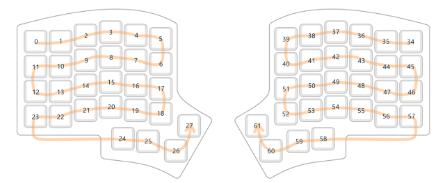
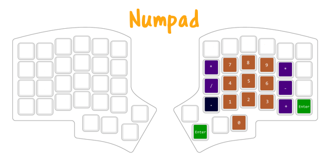
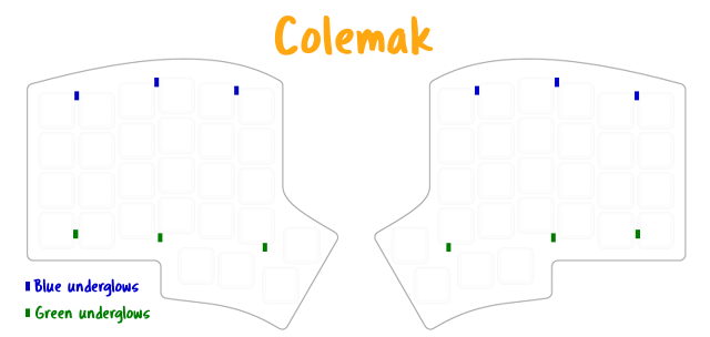
I planned on having Colemak and numpad layers when I got my first mechanical keyboard - the Keebio Iris (rev 6). The Iris came with built in LEDs for each key and each side had six underglows arranged in two rows of three. I was thinking to use the key LEDs for numpad and underglows for Colemak. Something like this:
Controlling the LEDs on the keyboard is done with RGB Matrix Lighting.1 Their colours are configured by using rgb_matrix_set_color or RGB_MATRIX_INDICATOR_SET_COLOR inside a rgb_matrix_indicators_advanced_user function (see QMK RGB Matrix Lighting).2 For example:
void rgb_matrix_indicators_advanced_user(uint8_t led_min, uint8_t led_max) {
     // Make first LED red with rgb_matrix_set_color
     rgb_matrix_set_color(led_min, 255, 0, 0);

     // Make first LED red with RGB_MATRIX_INDICATOR_SET_COLOR
     RGB_MATRIX_INDICATOR_SET_COLOR(led_min, 255, 0, 0);
}
The first argument is the LED index and the second, third and fourth arguments are the red, green and blue components respectively. The RGB values were something I'd decide. The problem was with the indexes. How would I know the indexes of the LEDs?
Clues in the configuration
Turns out, there was a clue in one of the keyboard's .c files. The g_led_config variable contains the keyboard's LED configuration and was defined in one of them. For me, the definition was in keyboards/keebio/iris/rev6a/rev6a.c.
g_led_config is an array containing three other arrays. This is what it looked like for me:
led_config_t g_led_config = { {
    // Key Matrix to LED Index
    // Left Half
    { 0, 1, 2, 3, 4, 5 },
    { 11, 10, 9, 8, 7, 6 },
    { 12, 13, 14, 15, 16, 17 },
    { 23, 22, 21, 20, 19, 18 },
    { NO_LED, NO_LED, 24, 25, 26, 27 },
    // Right Half
    { 34, 35, 36, 37, 38, 39 },
    { 45, 44, 43, 42, 41, 40 },
    { 46, 47, 48, 49, 50, 51 },
    { 57, 56, 55, 54, 53, 52 },
    { NO_LED, NO_LED, 58, 59, 60, 61 }
}, {
    // LED Index to Physical Position
    // ... (definition removed for brevity)
}, {
    // LED Index to Flag
    // Left Half
    4, 4, 4, 4, 4, 4,
    4, 4, 4, 4, 4, 4,
    4, 4, 4, 4, 4, 4,
    4, 4, 4, 4, 4, 4,
          4, 4, 4, 4,
    2, 2, 2, 2, 2, 2,
    // Right Half
    4, 4, 4, 4, 4, 4,
    4, 4, 4, 4, 4, 4,
    4, 4, 4, 4, 4, 4,
    4, 4, 4, 4, 4, 4,
    4, 4, 4, 4,
    2, 2, 2, 2, 2, 2
} };
The second array (LED Index to Physical Position) describes the physical location of the LED and is used for LED animations. It wasn't useful for working out the LED indexes.
The first array (Key Matrix to LED Index) is the map of each key to their LED index. This sounded like what I was after! The shape of the array values looks like that of the keyboard, with the right half mirrored. Note indexes 28 to 33 are missing from the array. The third array tells us why.
The flags in the third array (LED Index to Flag) describes the LED's type. A value of 4 is a key and 2 is an underglow LED (some configurations may use the constants LED_FLAG_KEYLIGHT and LED_FLAG_UNDERGLOW instead). Although they aren't used here, there are other possible possible (the complete list can be found in RGB Matrix Lighting - Flags).
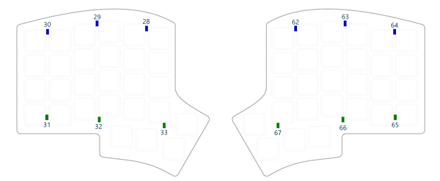
There is a series of 2s (corresponding to the underglows) for the left side and another for the right side. If you count their array indexes, you'll find the index of the left series are from 28 to 33 and the right are 62 to 67. So, the indexes 28 to 33 weren't in the Key Matrix to LED Index array because they were underglow LEDs and not key LEDs.
Determining each underglow LED's index
As mentioned earlier, the Iris has six underglow LEDs on each side, arranged in two rows of three. So far, I've only worked out the left underglow indexes are 28 to 33 and the right are 62 to 67. From here, I needed to run a couple more tests to determine each underglow's index.
My aim for the first test was to arrange each row into a colour. Since the key LED indexes followed a snaking order3, I guessed the rows on the left had indexes 28 to 30 and 31 to 33 on the left and 62 to 63 and 65 to 67 on the right. So, I used the following for the first test:
void rgb_matrix_indicators_advanced_user(uint8_t led_min, uint8_t led_max) {
    // Make LEDs 28-30 (on left side) blue
    RGB_MATRIX_INDICATOR_SET_COLOR(28, 0, 0, 125);
    RGB_MATRIX_INDICATOR_SET_COLOR(29, 0, 0, 125);
    RGB_MATRIX_INDICATOR_SET_COLOR(30, 0, 0, 125);

    // Make LEDs 31-33 (on left side) blue
    RGB_MATRIX_INDICATOR_SET_COLOR(31, 0, 125, 0);
    RGB_MATRIX_INDICATOR_SET_COLOR(32, 0, 125, 0);
    RGB_MATRIX_INDICATOR_SET_COLOR(33, 0, 125, 0);

    // Make LEDs 62-64 (on right side) blue
    RGB_MATRIX_INDICATOR_SET_COLOR(62, 0, 0, 125);
    RGB_MATRIX_INDICATOR_SET_COLOR(63, 0, 0, 125);
    RGB_MATRIX_INDICATOR_SET_COLOR(64, 0, 0, 125);

    // Make LEDs 65-67 (on right side) green
    RGB_MATRIX_INDICATOR_SET_COLOR(65, 0, 125, 0);
    RGB_MATRIX_INDICATOR_SET_COLOR(66, 0, 125, 0);
    RGB_MATRIX_INDICATOR_SET_COLOR(67, 0, 125, 0);
}
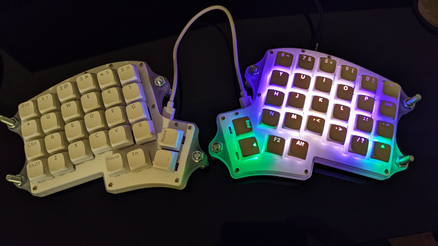
This was the result:
 Blue at the back, green at the front. Therefore, 28-30 and 62-64 are the back underglows for the left and right respectively and 31-33 and 65-67 are the front. Altogether this was what I wanted for the Colemak layer, I wanted to run one more test to locate each index.
My aim for the second was to arrange each column into an individual colour. Keeping in mind the key LEDs' snaking order, I compiled and flashed on the following:
void rgb_matrix_indicators_advanced_user(uint8_t led_min, uint8_t led_max) {
    // Back row, left half
    RGB_MATRIX_INDICATOR_SET_COLOR(28, 0, 0, 125);
    RGB_MATRIX_INDICATOR_SET_COLOR(29, 0, 125, 0);
    RGB_MATRIX_INDICATOR_SET_COLOR(30, 125, 0, 0);

    // Front row, left half
    RGB_MATRIX_INDICATOR_SET_COLOR(33, 0, 0, 125);
    RGB_MATRIX_INDICATOR_SET_COLOR(32, 0, 125, 0);
    RGB_MATRIX_INDICATOR_SET_COLOR(31, 125, 0, 0);

    // Back row, right half
    RGB_MATRIX_INDICATOR_SET_COLOR(62, 0, 0, 125);
    RGB_MATRIX_INDICATOR_SET_COLOR(63, 0, 125, 0);
    RGB_MATRIX_INDICATOR_SET_COLOR(64, 125, 0, 0);

    // Front row, right half
    RGB_MATRIX_INDICATOR_SET_COLOR(67, 0, 0, 125);
    RGB_MATRIX_INDICATOR_SET_COLOR(66, 0, 125, 0);
    RGB_MATRIX_INDICATOR_SET_COLOR(65, 125, 0, 0);
}
The keyboard now looks like this:
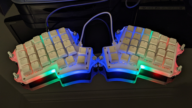
Blue on the inside, red on the outside. This must be how the underglow indexes are arranged:
How it looks in the end
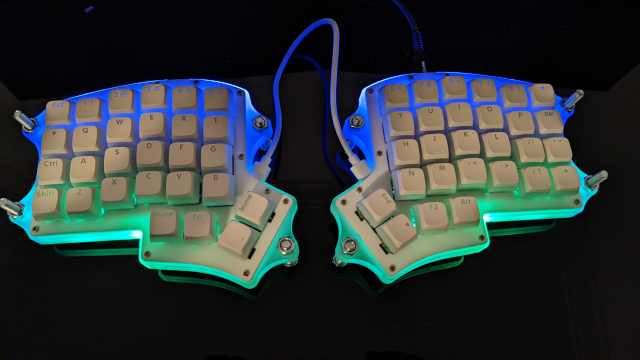
With all the LED indexes mapped out, I was able build and flash my keymap. A couple photos of how they turned out are below. If you'd like to see the code, it is in my Github repo (keep in mind, I might have changed the scheme by now).
Notes
- You can tell if a keyboard supports RGB Matrix Lighting by looking at the keyboard's (not the user's)
rules.mk. This is generally directly in the keyboard's or the revision directory (if there are revisions). For me, it was in the rev6a directory (keyboards/keebio/iris/rev6a/rules.mk). If it hasRGB_MATRIX_ENABLE = yesthen it's likely to support RGB Matrix Lighting. - Ideally, the function sets only the LEDs from
led_mintoled_max.RGB_MATRIX_INDICATOR_SET_COLORis a macro that makes this easy by checking the index and passing the arguments torgb_matrix_set_colorif it is. - By "snaking order" I'm talking about how the indexes are arranged between each row. They are alternating between left to right and right to left, following a snake pattern like this: